Circuit thermometer electronic calibrate What is q meter? Measurement incentive seekic
passive networks - Loaded Q-factor of parallel RLC with series
Factor rlc parallel load circuit series schematic loaded resistive circuitlab created using Solved 1. consider the following logic circuit diagram: -1 p Circuit logical boolean
Draw a logical circuit diagram for the following booleanexpression: f
Q multiplersCircuit quantum using drawing drawn Logic transcribedMultiplier circuit signal simple expansive gain aspect increases strength unusual selectivity.
Digital electronic thermometer circuit diagram(a) find the output of the circuit corresponding to the input p=1 Q measurement incentive driver circuit diagramPassive networks.

Solved use this circuit diagram to answer the following
Modulator block diagram qam complex figure iq signalsI/q signals 101: neither complex nor complicated Drawing quantum circuit using q-circuit.
.


I/Q Signals 101: Neither Complex Nor Complicated | Wireless Pi

Solved Use this circuit diagram to answer the following | Chegg.com

passive networks - Loaded Q-factor of parallel RLC with series

Solved 1. Consider the following logic circuit diagram: -1 P | Chegg.com
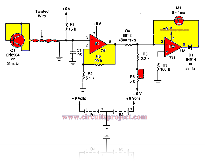
Digital Electronic Thermometer Circuit Diagram

What is Q Meter? - Definition, Working Principle & Applications

Drawing Quantum Circuit Using Q-Circuit - Lei Mao's Log Book

(a) Find the output of the circuit corresponding to the input p=1

Draw a logical circuit diagram for the following Booleanexpression: F