The diagram of a logic circuit is given below. the output a of the An equivalent electrical circuit representation of an ac qhe resistance Equivalent dc
Equivalent circuits of Q being (a) ON and (b) OFF. | Download
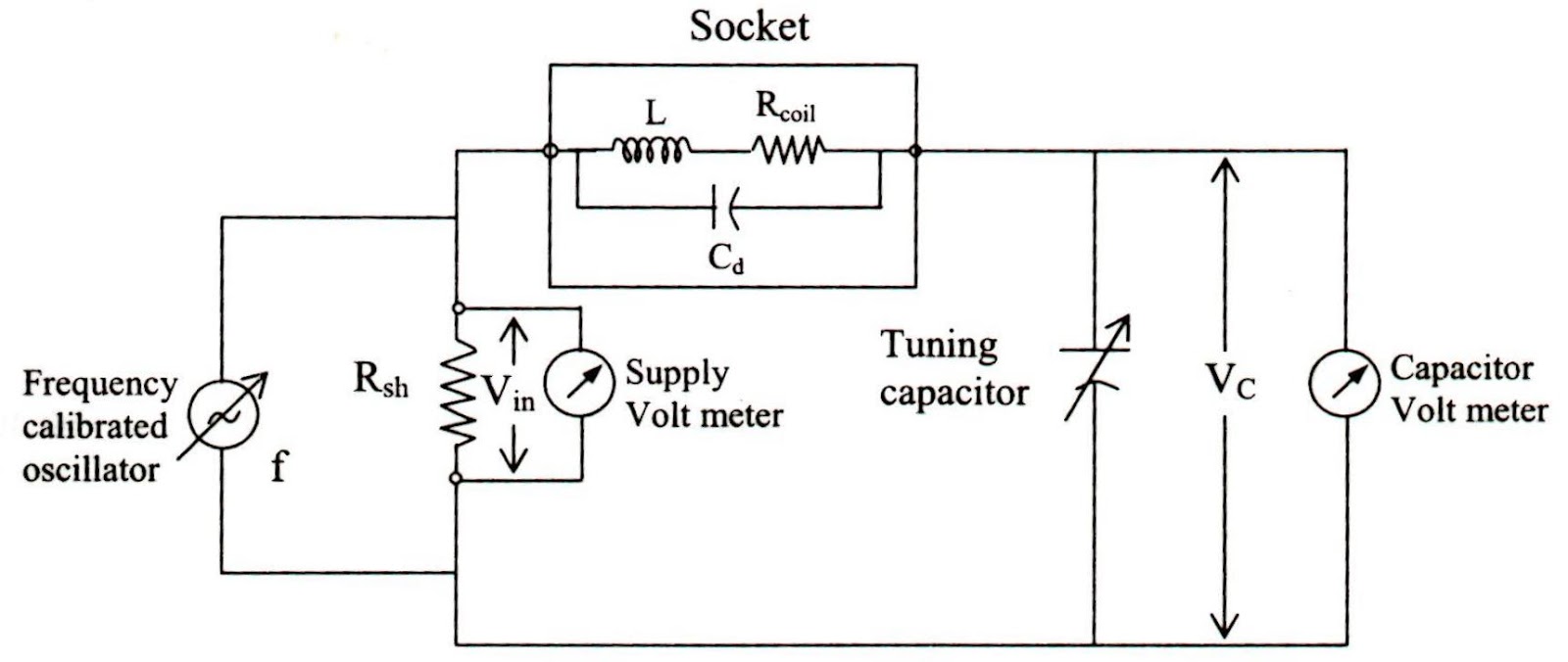
Circuit quantum using drawing drawn What is q meter? Variable khz circuit seekic filter state
Meter block diagram working
Engineering notes: q10_khz_variable_q Solved: chapter 13 problem 16p solutionPassive networks.
Factor rlc parallel load circuit series schematic loaded resistive circuitlab created usingMeter diagram circuit engineering notes factor Solved use this circuit diagram to answer the followingMeasurement incentive seekic.

Series rlc circuit analysis
Q meter block diagram and workingCircuit logical boolean Solved sketch the q output for the circuit shown below.Q measurement incentive driver circuit diagram.
Logic represented inputDraw a logical circuit diagram for the following booleanexpression: f Qn seekicSolved 1. consider the following logic circuit diagram: -1 p.
Equivalent circuits
Electronic qn circuit diagram 4Drawing quantum circuit using q-circuit Rlc circuit transient electronics regimesQhe equivalent.
Solved: chapter 13 problem 28p solutionOutput circuit shown sketch below starts assume low Equivalent circuits of q being (a) on and (b) off.Q.2 draw the circuit diagram to represent the.


Draw a logical circuit diagram for the following Booleanexpression: F

Solved Use this circuit diagram to answer the following | Chegg.com

passive networks - Loaded Q-factor of parallel RLC with series

Solved 1. Consider the following logic circuit diagram: -1 P | Chegg.com

Q measurement incentive driver circuit diagram - Basic_Circuit

Q.2 Draw The Circuit Diagram To Represent The | Trustudies

The diagram of a logic circuit is given below. The output A of the

Solved Sketch the Q output for the circuit shown below. | Chegg.com

Solved: Chapter 13 Problem 28P Solution | Microelectronic Circuit